ORD Tips and Tricks
Table of contents
- Attaching reference files
- Using the ribbon search bar
- Levels
- Working with arrows on basin delineations
- Find and replace text
- Creating keyboard shortcuts
- Adding pattern fill around an interior shape
- Rotating Elements
- Clip Mask an Annotation Bubble
- Finding URN address in ProjectWise
- Troubleshooting broken associations
- Troubleshooting axis lock
- Troubleshooting broken paths in Parametrix files
- Troubleshooting Toe of Fill offsets
This document covers the basics of the ORD tools and features we most commonly use at S&C.
Attaching reference files
To add a reference file:
-
Click the dropdown arrow on Primary > Attach Tools icon:

-
Click References
-
In the dialog box, go to Tools (in the menu) > Attach
- If the file you’re looking for isn’t there, try changing the file selection from “.dgn” to “all documents”.
-
Make sure all references are attached using Coincident World
- Coincident World keeps the coordinate system set in the seed file.
-
Typical references for all files:
- Topo
- Existing Surface
- Proposed Surface (often not available in early stages of a project)
- Aerial Imagery
- Design Files
- Alignment
Using the ribbon search bar
The ORD ribbon search bar is a powerful tool that makes finding tools and dialogs easier.
- You can quickly access the search bar by pressing F4.
- Search for terms in the text box or use the dropdown arrow to view your recent searches.
- Hover over search results to see the location of the search result item in the ribbon.
Levels
A “level” defines different layers or sections within a design, such as road surfaces, subgrades, utilities, and structures.
Toggle the Level Display on or off with the Level Display icon: 
Or use the ribbon search bar to search for “Level Display.”
How to display a level
-
Navigate to the Level Display pane.
-
Right click the level you want to display.
-
Check Display:

- Displayed levels will appear black in the Level Display pane while levels that aren’t displayed will be grey.
How to create a new level
-
Right click anywhere in the Child Level box, then click Level Manager:
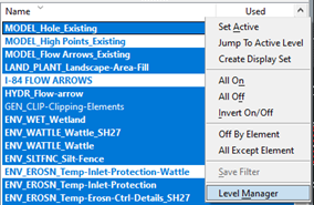
-
Click Levels > New or the New Level icon:

How to view and change the level of an element
-
To view the level of an element, click the element, then hover over it to see information about the element.
-
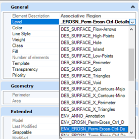
To change the level of an element, go to Properties > General, click Level, then select the new level from the dropdown:
How to set a level as active
-
Double-click the level to turn it from blue to green.
-
Alternatively, right click the level, then click Set Active.
Working with arrows on basin delineations
Use arrows to demarcate water flow directions and identify whether a basin is a shed or crown.
Placing a new arrow
-
Go to Drawing > Placement > Place Active Cell:

-
In the Place Active Cell dialog box, click … next to the Active Cell text box:

-
Click Display All Cells.

-
Find the cell library with the straight and wavy arrow cell.
-
Place the arrow on the appropriate level in the Plan view.
Moving arrows
Arrows should be placed perpendicular to the contour lines. To move an arrow:
-
Select the arrow .
-
In the ribbon (or use Search), click Move or Copy.
-
Place the arrow on a contour line.
-
In the ribbon (or use Search), select Rotate.
-
In the Rotate properties pane, set the Method to 3 points.
-
Click the center of the arrow you want to rotate, then click somewhere outside the arrow.
-
Then, use your mouse to rotate the arrow so it’s 90° perpendicular to the contour line.
Find and replace text
Use Find and Replace to replace text in a file with something else. Learn more in Bentley’s Help documentation.
-
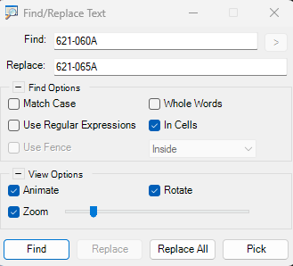
Navigate to the ribbon search bar and search for “replace.”
-
Select Find/ Replace Text.
-
Enter the term you want to replace in the Find text bar.
-
Enter the term you want to replace it with in the Replace text bar.
-
Click Replace All.
- Note that this will replace all the instances of the text in the file. If you only want to replace the text in a certain element or portion of the file, be sure to highlight the area you want to replace text in (multi-select by holding the left mouse button down and dragging from the lower right hand corner).
Creating keyboard shortcuts
To create your own keyboard shortcuts for your most frequently used tools:
-
Access the keyboard shortcuts by either searching “shortcuts” or go to File > Settings > User > Keyboard Shortcuts.
- You’ll need to know the key-in for the action or tool you want to create the shortcut for. You can learn more about key-ins on Bentley’s Microstation Help website - check out the Key-in Index at the bottom of the left-hand menu.
-
Click the Add button to add a new shortcut.
-
Alternatively, you can create a child shortcut. A child shortcut is triggered by first pressing the parent key, then the child key:
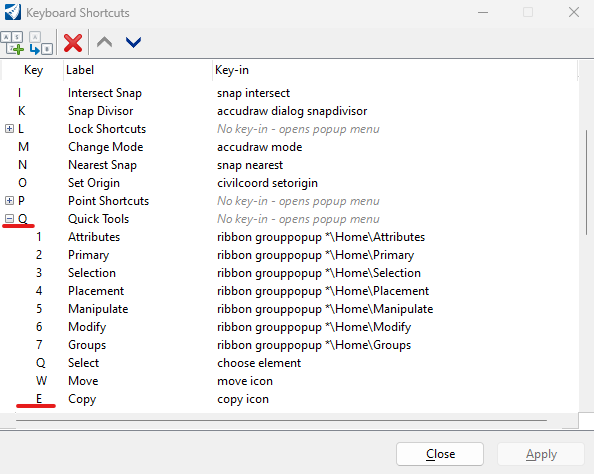
For example, in the above image, Q has several children shortcuts. To use Copy, you’d first press Q, followed by E. To Select, you’d press Q, then press Q again.
Some useful shortcut key-ins that you might want to add to your shortcuts are:
| Name | Key-in |
|---|---|
| Element Selection | choose element |
| Break by dragline | trim break bydragline |
| Place line | place line |
| Create complex shape | create shape manual |
| Tentative snap | buttonaction tentative |
Adding pattern fill around an interior shape
If you want to add a pattern fill to an area with an internal shape, use the “locate interior shapes” option in the Pattern Area Properties:
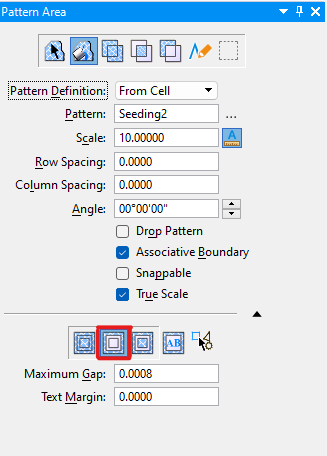
Then, when you select an area to fill, you’ll be able to add a pattern around a shape:
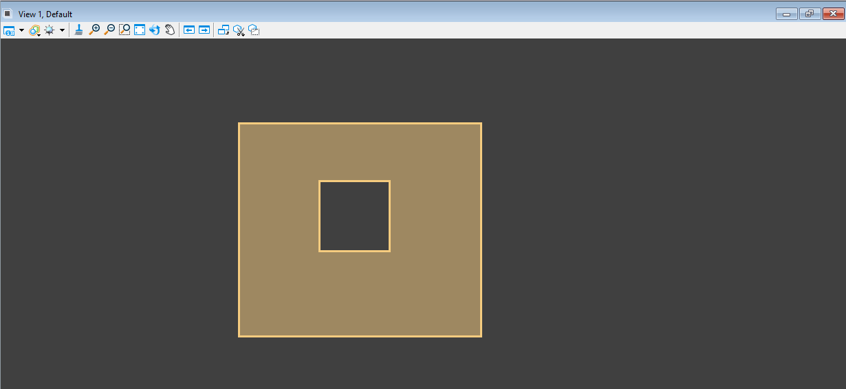
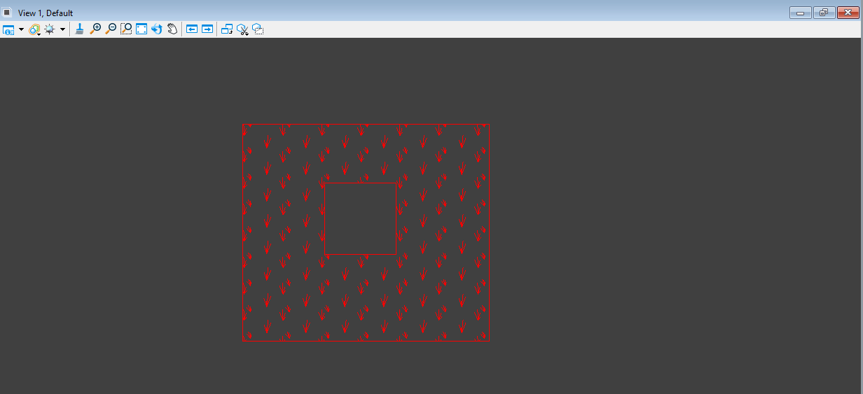
Rotating Elements
-
Use the Element Selection tool to highlight the element you want to rotate.
-
Select the Rotate tool.
-
Set the Method to 3 points, then click in the center of your element and then somewhere outside the element.
-
Use your mouse to rotate the element to the desired position.
Learn more about the rotate tool on Bentley’s Help portal.
Clip Mask an Annotation Bubble
-
Select the “Place Fence” tool.
-
Set the properties to Fence Type: Block or Fence Type: Element and Fence Mode: Inside.
- The block type lets you place a rectangle shape over an area, while element lets you place a fence within a specified element. Elements that can be used for a fence include closed planar elements (shapes, circles, ellipses, complex shapes, grouped holes). For annotation bubble call outs, you’ll need to place a planar element around the bubble to place a fence.
-
Place the fence over the area you want to clip.
-
Right-click the reference file to clip (usually the container file for Plan Sheets).
-
Select Clip Mask.
-
Click inside the fence
Finding URN address in ProjectWise
-
In ProjectWise, highlight the file you want the URN for.
-
In the Address bar, right click the file name.
-
Select Copy URN.
Troubleshooting broken associations
If the arrows on your seeding/ wattle bubbles are appearing as dashed lines, you may need to uncheck the Highlight Broken Associations option:
-
Navigate to File > Settings > Operation.
-
Uncheck Highlight Broken Associations.
Troubleshooting axis lock
If elements seem like they’re stuck on an x-y axis when you’re moving them, you might have to turn off Axis Lock for the file:
-
Navigate to File > Settings > File > Design File Settings.
-
Click Axis.
-
Uncheck Axis Lock.
Troubleshooting broken paths in Parametrix files
-
Right click on the file(s) that have broken links.
-
Click Set.
-
Scan references and link sets.
-
Click Next until you reach this dialog:
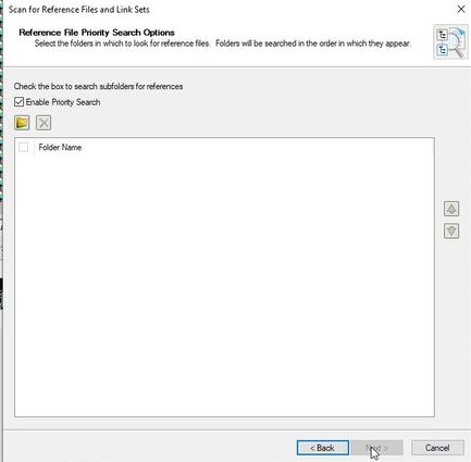
- Enter where the computer should look for the files.
- You may have to add multiple folders (design, location, hydraulics, sheets, etc.).
- Let it run the fix. It can take 15 minutes or so if you are fixing multiple files
Troubleshooting Toe of Fill offsets
If you can’t copy a parallel off of a Toe of Fill line in ORD:
-
Make a copy of the Toe of Fill line dots.
-
Paste the copied dots directly over the original ones.
-
Select Drop Element

-
Use the offset tool to create a line from the dropped element, then delete the copied Toe of Fill line.