Stormwater Basin Delineation in ORD
Table of contents
This page outlines how to create urban storm water basin delineations in ORD. Basin delineation should happen in the 2D design file.
For our purposes, a basin is an area where water collects and flows towards a central point or lower elevation. Basin delineation is the process of marking basin boundaries within a project’s scope. The purpose is to determine where and how much water is flowing to a location in order to set inlets, size swales, and begin the drainage design.
Proposed Basin Delineation
-
Open the 2D Design file.
-
Display the proposed terrain file level. See the Tips & Tricks page for more information on levels.
-
Display the proposed alignment (
ALGorALGN) file level. -
Identify if the road is a crown or shed section by looking at the contour lines in ORD and the typical section PDF file provided by the [prime].
- Contour lines are usually in the proposed terrain file, but can sometimes be in the corridor files.

-
Using the proposed surface (proposed terrain + proposed alignment = proposed surface), draw proposed drainage arrows throughout the project. See the Tips & Tricks for how to draw an arrow.
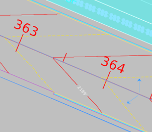
- Water flows perpendicular to the contour lines. In the illustration below, the contour lines are the red and yellow lines.

-
Proposed arrows should go on the
HYDR_BASIN_Flowpath-Proposedlevel as straight arrows. -
Existing arrows should go on the
HYDR_BASIN_Flowpath-Existinglevel as wavy arrows.

-
Click on the alignment line and hover over it.

-
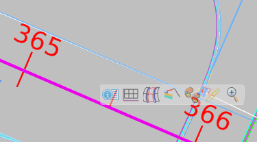
Select the Open Profile Model icon
- Open the profile model in another view port, either 5 or 6, on the bottom of the screen:

-
Identify high points and low points along the alignment.
- Write down the station number (x-axis on the bottom) at the high points and the low points somewhere else.

-
Return to the Plan view by clicking the close button, then set your active level to
HYDR_BASIN_Flowpath-Proposed. -
Draw the identified high point and low points in the plan view using the Place Line tool.
-
Draw the proposed impervious drainage basin based on the proposed surface, identified high points and low points, and typical sections.
-
Keep impervious and pervious basins separate. This will make it easier to calculate areas for the basins.
-
Put the impervious and pervious basins on different levels. See Tips & Tricks for how to create new levels.
-
Follow the naming conventions for the new level and add
PERVorIMPERV. -
Notice that SH4 is a shed section based on the arrows. Sh5 and SH6 are crown sections. So three basins will have been delineated.
-
-
Identify the pervious drainage areas and create complex shapes
-
The Complex Shapes tool is located at Drawing > Groups > Complex Shapes
-
Only draw shapes up to the ROW (right-of-way) line unless instructed otherwise. Attach the ROW reference file to make sure you are staying within the ROW.
-
Make sure to use the Complex Shape tool to make the basins a shape, rather than a bunch of lines. This will let you to get the accurate area measurement of the shape.
-
-
Create a new, separate level, called something like
ANNO_Pervious_AreasorANNO_Impervious_Areas. -
On this new level, annotate the areas of each basin for the Principal Engineer.
-
When you create the new level, turn off Print for both
ANNOlevels. -
Use the Place Text tool to record the area.
-
Use a naming convention like
SH4_IP=100sq ftorSH4_P=100sq ft. (SH4 = the basin name, IP/P = impervious/ pervious, then the measured area for the shape).
-
Existing Drainage Basin Delineation
-
Follow all the steps above, but use the existing terrain file level, rather than the proposed surface file level.
-
Place all delineations on existing conditions levels such as
HYDR_Flowpath_ExistingorHYDR_Drainage_Basin-Existing
